CNC turning machines are widely used in manufacturing industries for precision machining of cylindrical components. To operate efficiently, it’s important to understand the main parts of a CNC lathe and their specific functions. This article explains each component of a CNC turning machine with reference to the image shown above.
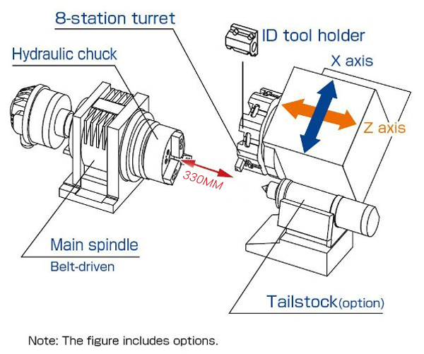
The main spindle is the heart of the CNC lathe. It rotates the workpiece at various speeds based on the machining operation. It is usually belt-driven or direct-drive depending on the machine design. The spindle speed is controlled through G-code commands (like S1000 M03) for clockwise rotation.
The hydraulic chuck is mounted on the spindle nose and is used to grip the workpiece securely. It operates using hydraulic pressure to open and close the jaws.
Function: Holds the material during machining.
Example: M10 – Clamp the chuck, M11 – Unclamp the chuck.
This ensures stability and precision even at high spindle speeds.
The turret is a rotating tool holder that can hold multiple tools (commonly 8 stations or more).
Each station can carry a turning, facing, boring, or threading tool.
The turret indexes automatically to the required tool position using the T code (e.g., T0101, T0202).
This allows multiple operations like facing, turning, grooving, and threading to be performed without manual tool change
The ID (Internal Diameter) tool holder is used for internal operations such as boring, internal threading, or grooving. It is mounted on the turret and aligned with the spindle axis for precision.
The CNC lathe uses two main axes of motion:
X Axis: Controls the tool’s movement toward and away from the center (diameter control).
Z Axis: Controls the tool’s movement along the spindle axis (length control).
For example:
G00 X50 Z0 → Rapid positioning near the workpiece.
G01 X0 Z-20 F0.2 → Linear cutting move.
These axes are servo-controlled to ensure accuracy and repeatability.
The tailstock provides additional support for long workpieces. It can hold a center or drilling tool to maintain alignment during machining.
It’s especially useful when turning shafts or rods longer than 200mm
The machining length of 330mm shown in the figure indicates the maximum workpiece length that can be machined within the available Z-axis travel range. This value varies based on the machine model.
In belt-driven designs, the spindle receives power from a motor via a timing belt. This system allows variable speed control and absorbs shock loads effectively. Newer machines may use direct-drive spindles for better torque and reduced vibration.
Every CNC turning machine component plays a vital role in ensuring accuracy, stability, and productivity. Understanding each part helps operators set up, program, and maintain machines effectively.
If you’re looking to learn CNC programming, G-code, M-code, and machine operation in detail, explore our TSRCNC e-learning app — designed for machinists and engineers who want to master industrial CNC technology